Creating a pocket pentest platform with P4wnP1: Part 1
Intro⌗
Those in the security community are most likely familiar with the USB rubber ducky. On the off chance that you haven’t heard of it, the ducky is a device with the form factor of a standard USB drive. However instead of simply storing files, the rubber ducky can emulate a Human Interface Device (HID) such as a keyboard and mouse. It can preform any task you would be able to using these devices, except it can type at the speed of a computer.
This allows an attacker to plug in the ducky, deliver their payload at lightning speed, and get the hell out.
That being said, the ducky has some limitations. First of all, it is $50 for a single unit, which seems like a lot for a tiny flash drive with a single capability. Secondly, the default language “Duckyscript” does not allow for particularly advanced payloads. Payloads can be selected with physical dip switches on the device.
Then I heard about P4wnP1, which solves many of the issues mentioned above. P4wnP1 runs on a raspberry pi, a tiny but fully featured linux computer. This means that on top of the HID injection features of the rubber ducky, there is a lightweight installation of Kali Linux under the hood, ready for you to use as a malicious AP, pivot box, network sniffer, or whatever else you would do with Kali.
Required hardware:⌗
Here is a list of the hardware I used for this project.
| Item | Price |
|---|---|
| Raspberry pi 0W | $10 |
| GPIO pins | $7.97 |
| OLED display hat | $16.95 |
| Micro SD card(s) | $16.98 |
| USB A addon board | $8.99 |
| 3D printed case | Free from work |
| Total | $60.89 |
For only $10 more than the ducky, we can expand our feature set by a great amount. Not only this, but many of these items contain duplicates, (multiple SD cards and GPIO pin sets) so you could make many of these devices, or save money by buying individually packaged.
Installing P4wnP1⌗
Looking at the P4wnP1 readme, we can see there’s options for installing the P4wnP1 service on top of an existing linux distrobution, or installing the entire image to a fresh SD card.
Since we have fresh SD cards, this is by far the simplest method. Fire up your favorite image flasher (or use the dd command) and write the latest P4wnP1 image to your SD card. Most documentation recommends the etcher program to do this, so I figured I would give it a shot.
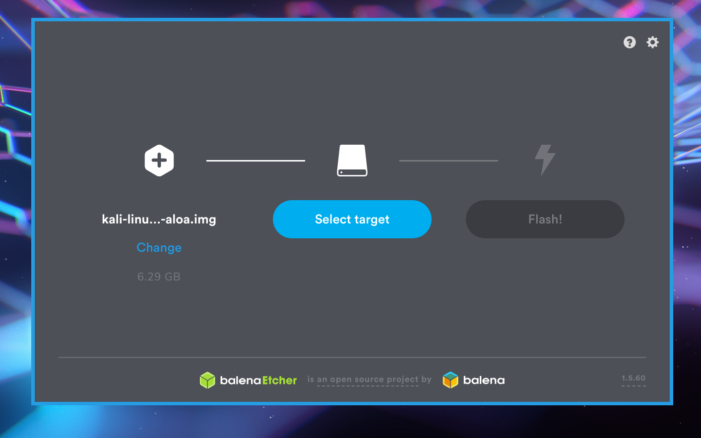
Open etcher as root, select your image, select your SD card, and flash away.
Once this step is complete, you have an SD card containing the P4wnP1 image, ready to roll in your raspberry pi.
Set up P4wnP1⌗
To set up your P4wnP1 for the first time, we can plug in a Micro USB cable from a PC into the pi.
Make sure that the correct “Data” port is being used instead of the power port. Do not interrupt the first boot of the P4wnP1, which can take a few minutes.
There are a few ways to connect to your pi. My preferred method is to use the PC the pi is connected to and navigate to http://172.16.0.1:8000 in a browser. This should open up the P4wnP1 web configuration page.
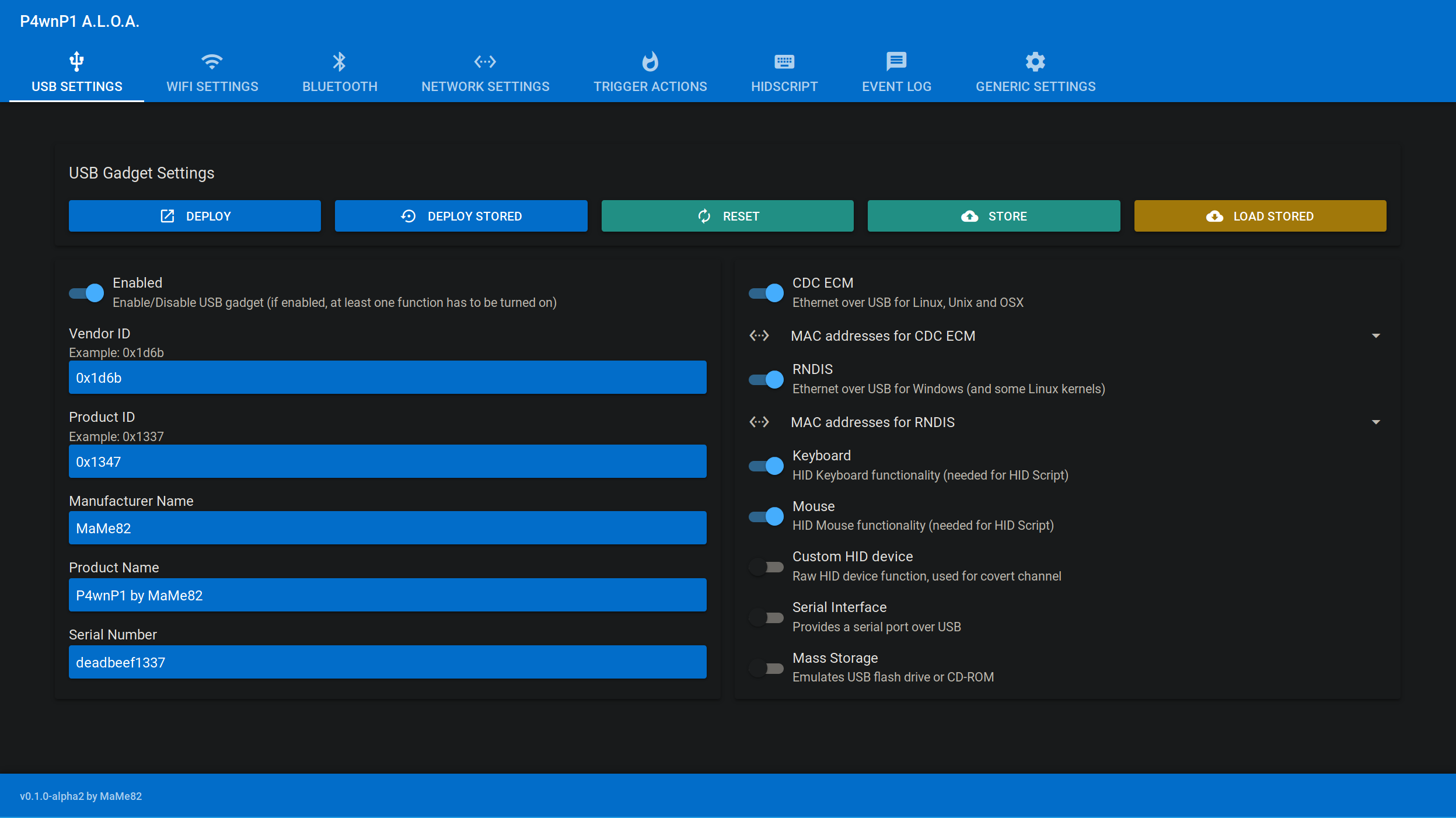
I will delve further into the settings and workflow in another post, as I am mainly focusing on getting the physical device set up here.
Additionally, you can connect to P4wnP1 by using the web interface to connect it to your WiFi network, and ssh to it with ssh root@172.16.0.1. Or connect your device to the AP
broadcasted by the P4wnP1, and ssh from that network. There is also a bluetooth configuration option, yet I have never tried it.
See the readme section for more info on how to connect to your P4wnP1.
Setting up the hardware⌗
Now that we confirmed we have a working raspberry pi, and a valid version of P4wnP1 flashed to our SD card, we can start working on the hardware.
The first step is to solder the GPIO pins to the raspberry pi. If you don’t have a soldering gun or are just a bit lazy, you can opt for a raspbery pi 0W with pre soldered pins.
Holding the raspberry pi upright, insert the pins short side down into the pinholes. Moving to the underside of the pi, apply a small drop of solder to each of the pins, so it makes a connection with the pad at the base of the pin.

Notice the plastic screws poking through the corners of the board. Those are the standoffs for the USB A addon board, which you can proceed to secure with the provided set of plastic nuts.
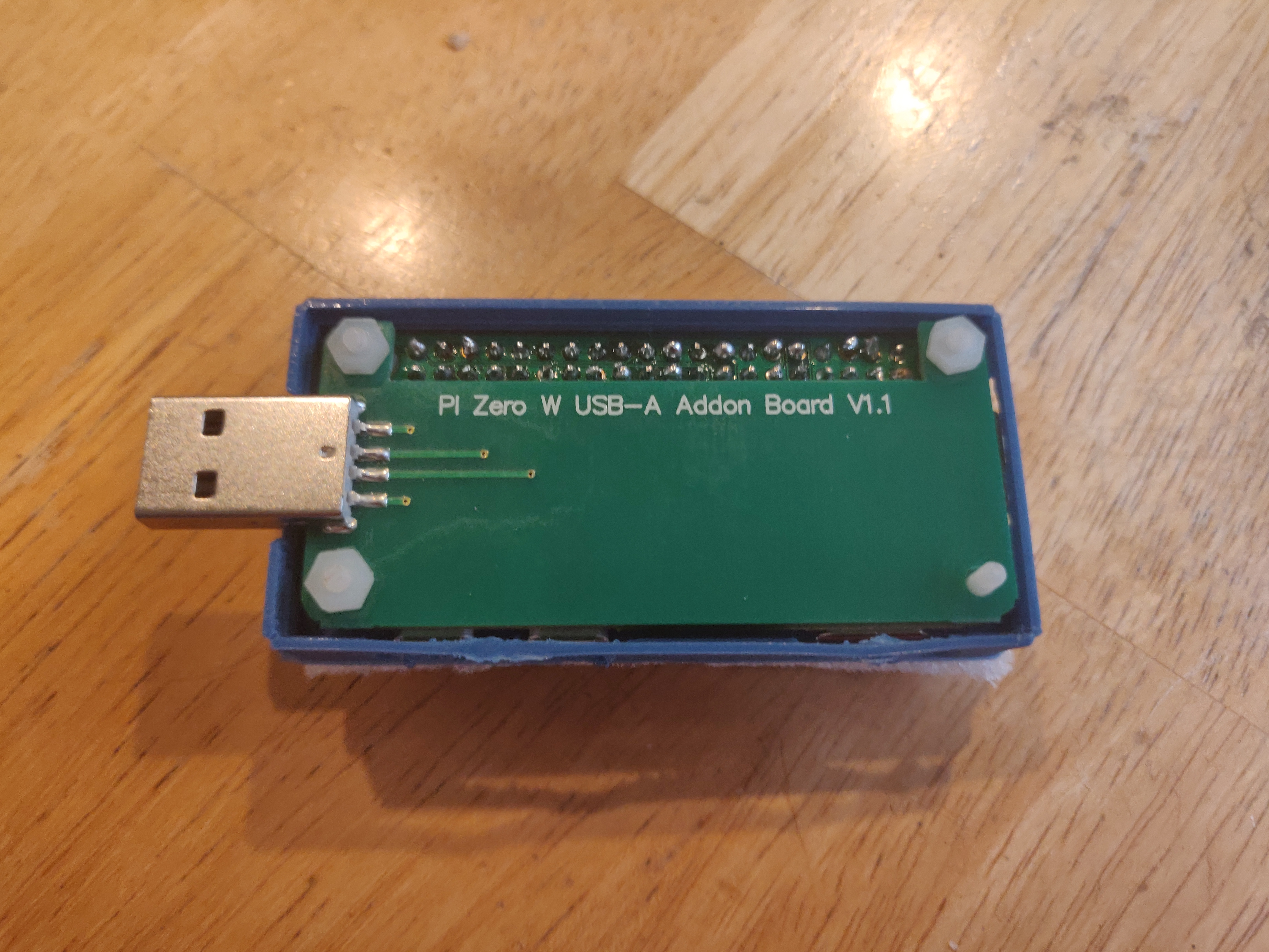
The USB A addon board should make a solid connection with the pads on the bottom of the pi. Test to see if it works by powering the pi over the USB A plug. This addon board allows us to preform ducky like attacks without carrying an additional micro USB -> USB A converter.
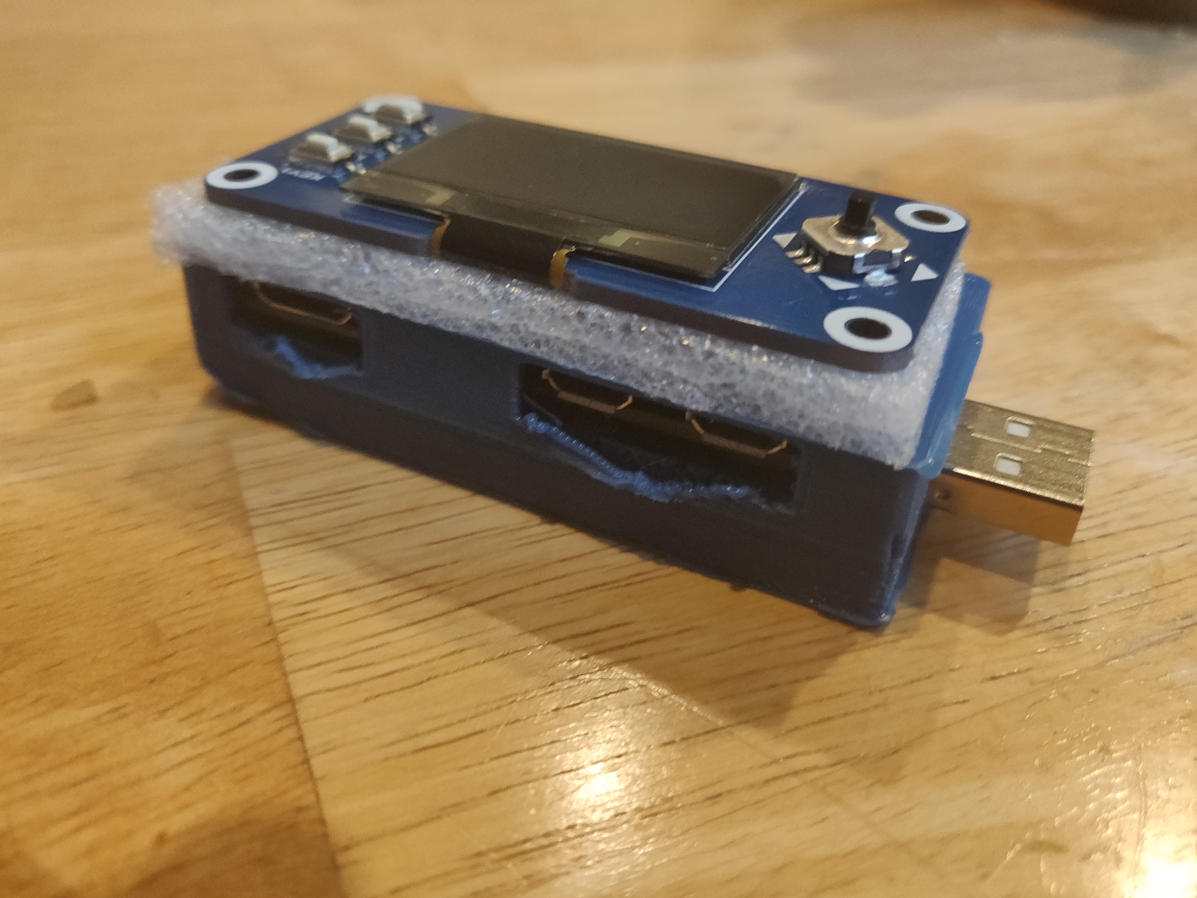
Finally, we can install the OLED screen hat using the GPIO pins we just soldered to the pi. This may take a bit of force, but the screen should press down over the IO pins.
I used a bit of the foam that the OLED hat was packaged with to brace the PCB against the 3D printed case.
Setting up the menu:⌗
For the OLED menu, we will be using the amazing menu by Beboxos. The full tutorial can be found in the readme, but I will outline the steps here, as it’s quite simple.
To enable the screen to for P4wnP1, we first have to edit the config.txt located in the boot partition of the SD card.
In the dtparam section, make sure the following lines are set:
dtparam=i2c_arm=on dtparam=i2c1=on
dtparam=spi=on
There is a section in the readme that mentions only one of these lines is necessary depending on your display, but I had the display he recommended on the Thingiverse page, so I left all the options on to be safe. Haven’t seen any issues so far with that.
Next, ssh into the pi with ssh root@17.16.0.1. Connect the pi to the internet through the web interface, and clone the
repository for this project. Inside it, you will find a script install.sh At the time of writing, this script was quite
buggy, and I had to fix it up a bit to get it working. Mostly just messed up filepaths and such.
#!/bin/sh
echo "Install Luma.core drivers"
apt-get install python-dev python-pip libfreetype6-dev libjpeg-dev
pip install --upgrade pip
apt-get purge python-pip
pip install --upgrade luma.oled
echo "Create directory"
mkdir /root/BeBoXGui/
echo "Copying files"
cp *.py /root/BeBoXGui/
mkdir /root/BeBoXGui/images
cd images
cp * /root/BeBoXGui/images/
echo "Copying run script in local P4wnP1 script"
cp scripts/runmenu.sh /usr/local/P4wnP1/scripts/
echo "All files are ready"
echo "to run with P4wnP1 boot"
echo "Go thru web interface"
echo "Go in trigger section"
echo "Create new trigger"
echo "on service start :"
echo "run script sh and choose "
echo "runmenu.sh"
echo "Enjoy"
echo "by default gui.py use SPI interface"
echo "if you use I2C oled edit gui.py"
echo "and set I2C_USER = 1"
I would have created a PR for these fixes but there was an outstanding PR addressing the issue which has been ignored for some months now.
As you can see in the script, the script runmenu.sh was copied to /usr/local/P4wnP1/scripts/. As you might have guessed, running this script will in fact run the on screen
menu. The final step is to create a trigger action that runs that script when the P4wnP1 service starts.
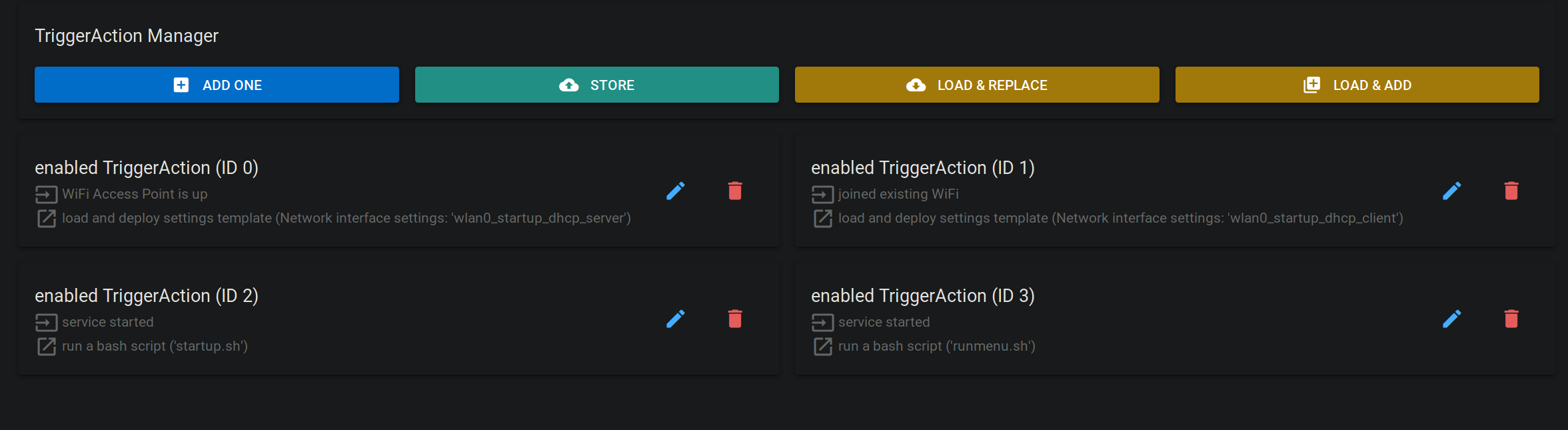
We can then store this trigger action set, and create a new “master template” in the Generic Settings menu that uses this stored trigger actions set.
This master template should inherit all other settings modules from startup as to not interfere with the process.
We can then make our newly created master template the default startup template using the field on the righthand side of the screen.
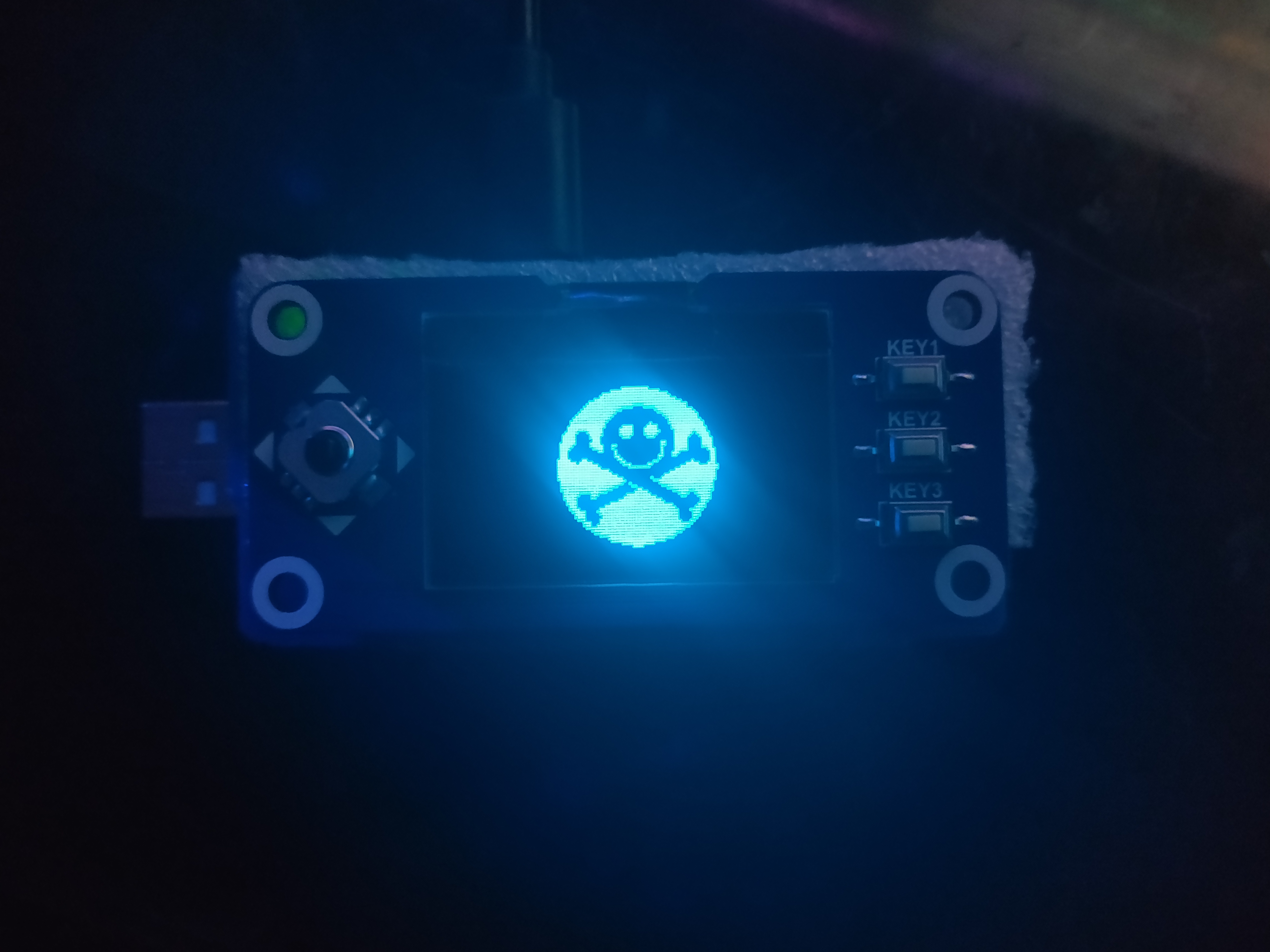
Now when you reboot the device, you should be greeted by the OLED menu!

I replaced the filename at this line with another file from the
images directory. You could totally make your own, I would love to see some cool ones.
We can see the main menu offering us a wide range of options.
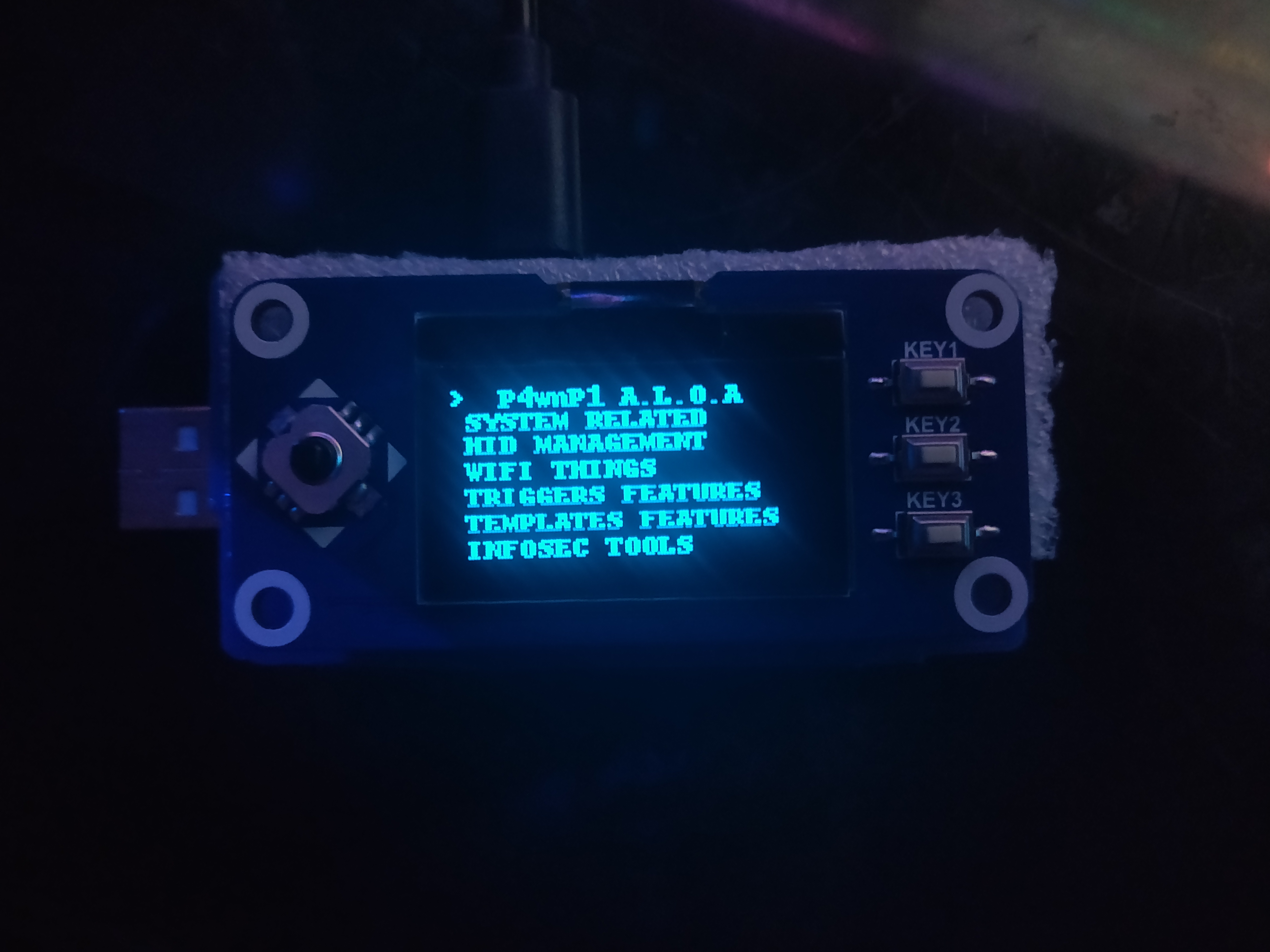
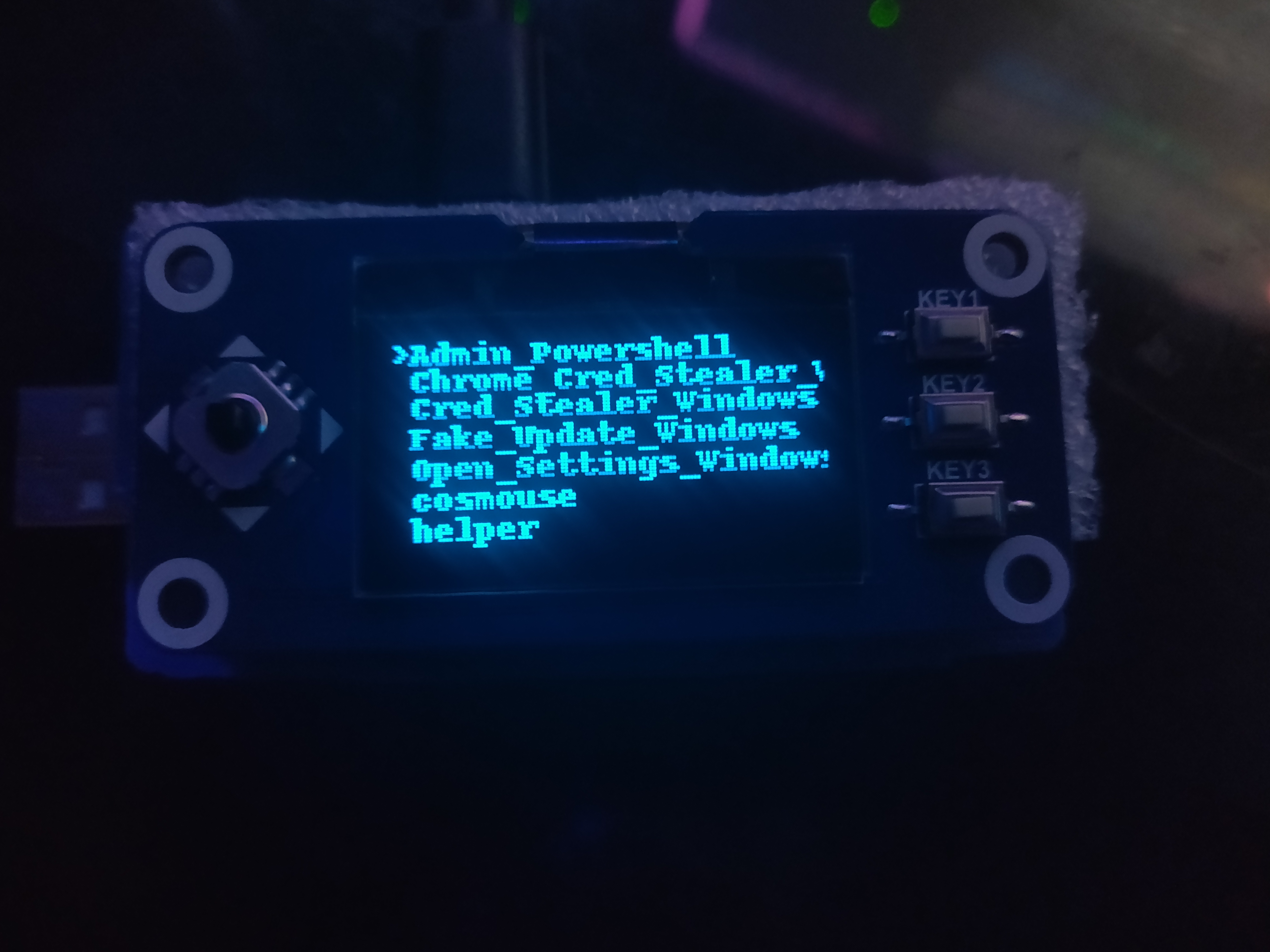
The main areas of interest to us are the HID Management and Templates Features sections. The HID Management section allows you to browse your stored HID scripts, and run them
as either a direct or background job.
 In
In Templates Features, we can browse and apply any saved settings templates for Network, Bluetooth, Wifi, USB, and Trigger actions. This allows you to easily set up more complex
attacks with complicated configurations without having to set them up via SSH or the web interface
Any settings applied through the menu should be instantly visible on the web interface.
The Case⌗
I happen to be lucky enough to work an environment where I have a 3D printer at my disposal. However I did not design the case myself, but I found it on Thingiverse, and printed out from there.
Eventually, I would like to modify this design to incorporate some sort of rechargeable battery. However since the screen is occupying the GPIO pins and the USB A addon is occupying the connection pads, there are limited options when it comes to connecting it.
One could forgo the USB A capabilities and instead use the connectors for a Pisugar, which provides a solderless rechargeable battery.
Or if someone wanted to make a screenless version, they could opt for a LiPo hat that uses multiple PCBs and the GPIO pins. This seems like it would be the bulkiest method.
Conclusion⌗
In this post, I showed you how to create a pocket sized pentest platform, with HID keystroke capabilities that are more robust than the USB rubber ducky, with the benefits of a powerful Kali Linux backbone for all your netsec needs.
In the near future I will elaborate on the effective P4wnP1 workflow, and some nifty examples of the powerful HID interface API.