Quantum Katas #1: Basic Quantum Gates
I have been fascinated with quantum computing since the day I learned of its existence.
I picked up the Microsoft Quantum Development Kit as soon as it was released, but being far from a quantum physicist, I was understandably lost.
Since then, I have done a fair bit of research on the subject, and Microsoft has released a set of tutorials called Quantum Katas to help developers get their feet wet in the world of quantum computing.
Using these Katas, I hope to introduce you to some fundamental concepts in quantum computing and quantum mechanics.
Getting ready to write quantum code⌗
In order to work with Quantum programs, you need to have your quantum development environment set up. This is as easy as installing Visual Studio or VS Code and installing the Microsoft Quantum Development Kit extension with the included extension manager.
In addition to this, you will need to have the dotnet runtime and development kit available to your system. On Arch Linux, this can be accomplished with
sudo pacman -Syu dotnet-runtime dotnet-sdk code
If everything went well, you should be able to run the quantum examples that come with the QDK.
Getting the Katas⌗
The Katas can be acquired from their github repository.
Usually I would do my development in Neovim, but I opted to stick with VS Code for this project because it is better integrated with the language (also being a Microsoft product). Syntax highlighting and other hints are nice to have when working with an unfamiliar language.
The Katas assume a test driven workflow, so you can track your progress through each tutorial. In the BasicGates folder, run the dotnet test command to run the Tests.qs file and test your solutions.
Before starting this guide, I recommend checking Microsoft's readings on the qubit, which goes over some of the mathematical and visual representations I will be using in this tutorial.
Task 1.1: State flip⌗
This is possibly the most basic quantum gate, with a counterpart in classical computation. Analogous to the classical NOT gate, the Pauli X gate takes a single qubit and flips its state.
That is, a qubit in state \(|0\rangle\) will be flipped to state \(|1\rangle\) and vice versa. This operation can be represented with the following linear transformations.
To generalize, the effect of the \(X\) gate on an arbitrary qubit is as follows:
Where \(\alpha\) and \(\beta\) are complex numbers that represent the probability of measuring the qubit in state \(|0\rangle\) and \(|1\rangle\) respectively. Simply fill the code in like so to complete this task.
operation StateFlip (q : Qubit) : Unit is Adj {
    X(q);
}
Quantum gates have the unique property of being reversible. For every unitary transformation \( U \), there exists an adjoint transformation \( U^\dagger \) that reverses the operation, such that
Like the classical NOT gate, the Pauli X gate has the property of being self-adjoint, meaning it is its own inverse. Applying the operation twice will result in the initial state. Multiple quantum operations can be represented as the matrix product of all the transformations.
Here we can see applying the X gate twice results in the identity matrix, meaning no transformation occurred.
Task 1.2: Basis change⌗
This is the first truly quantum gate we have encountered in this tutorial. This task requires the use of the Hadamard gate, which can be represented by the following unitary matrix.
In ket notation, the Hadamard gate looks like this.
\[ H(|0\rangle) = \frac{|0\rangle + |1\rangle}{\sqrt{2}} = |+\rangle \]
\[ H(|1\rangle) = \frac{|0\rangle - |1\rangle}{\sqrt{2}} = |-\rangle \]
And in matrix notation
This transformation takes the qubit from the computational basis \((|0\rangle |1\rangle)\) to the polar basis \((|+\rangle |-\rangle)\). To see the effect on the state of a qubit, let us consider the following qubit state
\[|\Psi \rangle = \alpha |0\rangle + \beta |1\rangle\]
where \(\alpha\) and \(\beta\) again represent the normalized probability amplitudes of the quantum state. By applying the Hadamard gate to this state, we can reduce the quantum state like so.
\[H(|\Psi \rangle) = H(\alpha |0\rangle + \beta |1\rangle) = \alpha \left(\frac{|0\rangle + |1\rangle}{\sqrt{2}}\right) + \beta \left(\frac{|0\rangle - |1\rangle}{\sqrt{2}}\right) = \frac{\alpha + \beta}{\sqrt{2}}|0\rangle + \frac{\alpha - \beta}{\sqrt{2}}|1\rangle \]
This transformation alters the probability amplitudes of the state. Like the X gate, the Hadamard gate is self adjoint.
To complete task two, fill in the operation like so
operation BasisChange (q : Qubit) : Unit is Adj {
    H(q);
}
Task 1.3: Sign flip⌗
The objective in this task is to take a qubit in the \(|+\rangle\) state and flip it to \(|-\rangle\), and vice versa.
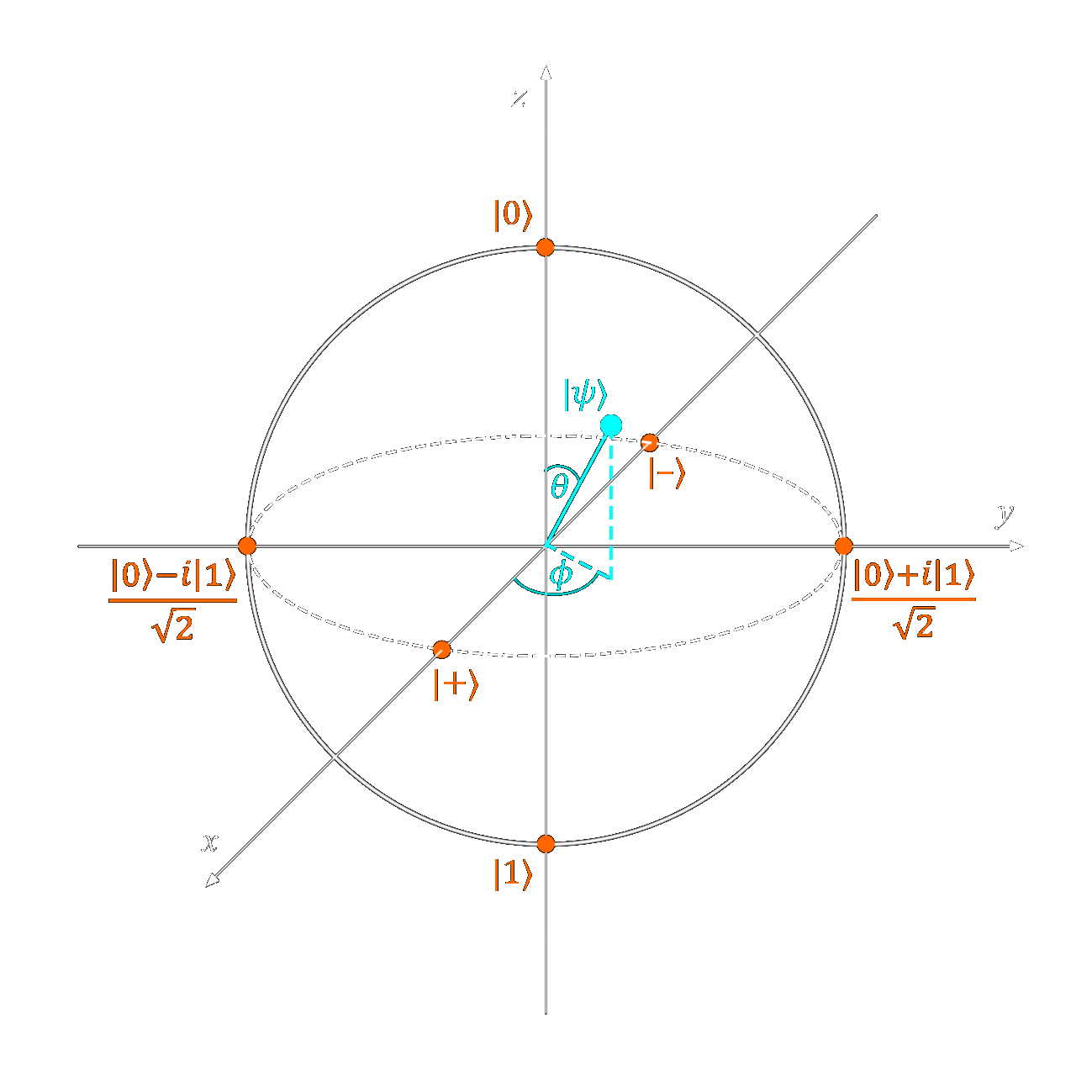
By looking at the Bloch sphere, we can see that the state \(|+\rangle\) or \(\frac{|0\rangle + |1\rangle}{\sqrt{2}}\) is represented by a vector pointing directly along the x axis in the positive direction. To negate this, we must make our quantum state vector point along the x axis in the negative direction.
This can be accomplished by rotating out vector \(\pi\) radians or \(180^\circ\) about the \(Z\) axis. Like the Pauli X gate rotated our state vector about the \(X\) axis, the Pauli Z gate will rotate our vector about the \(Z\) axis.
Like all of the Pauli gates, Pauli Z is self adjoint.
The effect of this quantum gate looks like this:
\[ Z(|\Psi\rangle) = Z(\alpha|0\rangle + \beta|1\rangle) = \alpha|0\rangle - \beta|1\rangle \]
Although \(\beta \rightarrow -\beta\), \(|-\beta|^2 + |\alpha|^2 = 1\) so normalization holds.
Fill in the operation like so to complete the task.
operation SignFlip (q : Qubit) : Unit is Adj {
    Z(q);
}
Task 1.4: Amplitude change⌗
In this section, our task is to change the amplitude of our qubit.
Looking at the Bloch sphere, we see that amplitude is represented by the angle \(\theta\), the angle measured between our state vector \(\Psi\) and the \(Z\) axis.
To change this angle, we must rotate out state vector about the \(Y\) axis. Looking at the documentation on the \(R_y\) operation, we can see it takes the form of the following unitary matrix.
The comments above this task provide the following hints:
If the qubit is in state |0⟩, change its state to cos(alpha)*|0⟩ + sin(alpha)*|1⟩.
If the qubit is in state |1⟩, change its state to -sin(alpha)*|0⟩ + cos(alpha)*|1⟩.
If the qubit is in superposition, change its state according to the effect on basis vectors.
operation AmplitudeChange (alpha : Double, q : Qubit) : Unit is Adj+Ctl {
Ry(2.0 * alpha, q);
}
Task 1.5: Phase Flip⌗
Our goal in this task is to take a qubit in the state \(|\Psi\rangle = \alpha|0\rangle + \beta|1\rangle\) and change it to state \(|\Psi\rangle = \alpha|0\rangle + i\beta|1\rangle\)
On the Bloch sphere, this would map our qubit's state from \(|X\rangle\) to \(|Y\rangle\), introducing an imaginary component to our \(|1\rangle\) term.
The perceptive may have noticed that this is simply a rotation about the \(Z\) axis by \(90^\circ\) or \(\frac{\pi}{2}\) radians. In fact, Quantum Inspire's page about the S gate explicitly says
The S gate is also known as the phase gate or the Z90 gate, because it represents a 90 degree rotation around the z-axis.
In physical terms, this changes the angle \(\Phi\) without altering \(\theta\), the angle between the vector and the \(Z\) axis.
In mathematical terms, we introduce an imaginary element into our \(|0\rangle\) component.
The \(S\) gate can be represented by the following matrix:
Fill in the following code to complete the operation:
operation PhaseFlip (q : Qubit) : Unit is Adj+Ctl {
    S(q);
}
Task 1.6: Phase change⌗
Let us remember that the phase of a qubit is represented by the angle \(\Phi\) on the bloch sphere. This is the angle made between the \(X\) axis and the projection of our state vector on the \(XY\) plane.
To alter this angle, we must rotate our state vector about the \(Z\) axis by \(\alpha\) degrees.
Using the knowledge we have gained so far, one might assume the \(\sigma_z\) or \(Z\) rotation gate could accomplish this. However, the following snippet will result in the test failing.
operation PhaseChange (alpha : Double, q : Qubit) : Unit is Adj+Ctl {
    Rz(alpha, q);
}
Looking at the solutions file, we see that the intended solution is the \(R1\) operation. This operation rotates the vector about the \(|1\rangle\) state.
operation PhaseChange (alpha : Double, q : Qubit) : Unit is Adj+Ctl {
    R1(alpha, q);
}
To be completely truthful, I am unsure why this is the case. The documentation for the \(R1\) operation says that it equivalent to R(PauliZ, theta, qubit);, or a rotation about the \(Z\) axis by theta degrees.
However, the test will fail if Rz or R operations are used. If anyone knows the reason behind this, please do enlighten me.
Bell States⌗
Before we continue to the next task, let us briefly unpack an important concept in quantum information.
To put it simply, a Bell state or EPR pair is a pair of maximally entangled qubits. The four Bell states are as follows.
\[ |\Psi^+\rangle = \frac{|01\rangle + |10\rangle }{\sqrt{2}} = |\beta_{01}\rangle \]
\[ |\Psi^-\rangle = \frac{|01\rangle - |10\rangle }{\sqrt{2}} = |\beta_{11}\rangle \]
\[ |\Phi^+\rangle = \frac{|00\rangle + |11\rangle }{\sqrt{2}} = |\beta_{00}\rangle \]
\[ |\Phi^-\rangle = \frac{|00\rangle - |11\rangle }{\sqrt{2}} = |\beta_{10}\rangle \]
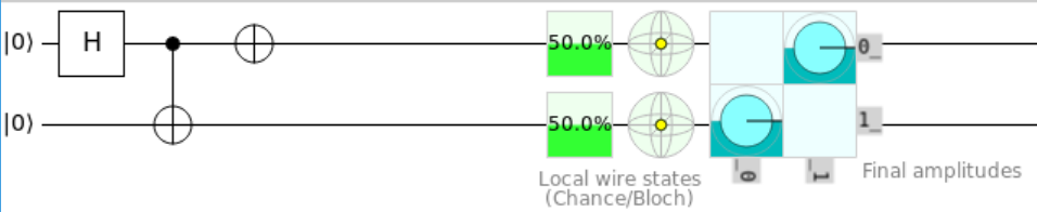
The arbitrary Bell state \(|\beta_{xy}\rangle\) can be prepared with the following quantum circuit.
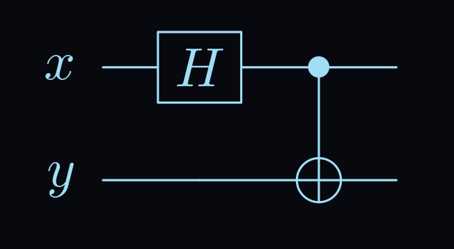
This diagram shows qubit \(x\) being put into the hadamard gate, which gives it a \(\frac{1}{2}\) chance of being found in the 0 and 1 position. Then, this qubit is used as the control in a CNOT gate. The state of qubit \(y\) will only be flipped if qubit \(x\) is in state \(|1\rangle\)
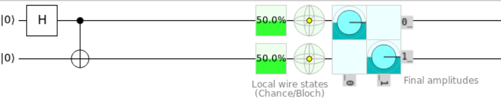
To see how this works in detail, check out this quantum circuit tool. Here I have prepared the \(|\Psi^+\rangle\) Bell state. Mess around with the inputs to generate the different states.
Task 1.7: Bell State Change 1⌗
Our goal in this task is to take two qubits prepared in the bell state \(|\Phi^+\rangle\) and transform them to the bell state \(|\Phi^-\rangle\)
We recall from task 1.3 that a sign flip of a single qubit state can be accomplished with the Pauli Z gate.
Can we extrapolate this to work on a multi-qubit state?
operation BellStateChange1 (qs : Qubit[]) : Unit is Adj+Ctl {
    Z(qs[0]);
    // alternatively Z(qs[1]);
}
Indeed we can. Applying the Z gate to either of the qubits will change them to the \(|\Phi^-\rangle\) state.
In Q#, a quantum register is treated like an array. Elements within the register can be indexed and operated upon for multi-qubit states and operations.
Task 1.8: Bell State Change 2⌗
In this task, we take the Bell state \(|\Phi^+\rangle\) to the state \(|\Psi^+\rangle\). Applying the Pauli X gate to one qubit in a Bell state will keep the sign the same but alter the possible measured values.
In simple terms, this would take \(|\Phi^\pm\rangle \rightarrow |\Psi^\pm\rangle\) and vice versa.
Fill in the operation like so to complete the task:
operation BellStateChange2 (qs : Qubit[]) : Unit is Adj+Ctl {
    X(qs[0]);
    // alternatively X(qs[1]);
}
Task 1.9: Bell State Change 3⌗
In our final Bell state task, we must combine the things we have learned so far to transform \(|\Phi^+\rangle\) to \(|\Psi^-\rangle\).
As you may have guessed, we can combine the X and Z gates to change the basis and sign.
operation BellStateChange3 (qs : Qubit[]) : Unit is Adj+Ctl {
    X(qs[0]);
    Z(qs[0]);
}
As the comment in the code mentions, this operation is not equivalent to Y(qs[0]), because the Y gate adds a global phase that the X and Z gates do not.
Task 2.1: Two-qubit gate - 1⌗
Let's closely examine the spec for this task to isolate what the true goal is here.
Goal: Change the two-qubit state to α |00⟩ + β |11⟩.
The keen eyed might recognize the measurement basis of \(|00\rangle\) and \(|11\rangle\) being the same as the Bell states \(|\Phi^\pm\rangle\)
The first qubit will be in state |ψ⟩ = α |0⟩ + β |1⟩, the second in state |0⟩
Since our first qubit is already in superposition, there is no need to apply the H gate. All that is left to do is apply a CNOT gate, using our first qubit as a control.
operation TwoQubitGate1 (qs : Qubit[]) : Unit is Adj {
    CNOT(qs[0], qs[1]);
}
We have just created a pair of entangled qubits. Unlike the Bell states, these qubits are not necessarily maximally entangled, with amplitudes \(\frac{1}{\sqrt{2}}\). The amplitudes \(\alpha\) and \(\beta\) can represent any complex normalized probability amplitude.
Task 2.2: Two-qubit gate - 2⌗
We have been given two qubits prepared in the \(|+\rangle\) state. Recall that
\[ |+\rangle = \frac{|0\rangle + |1\rangle}{\sqrt{2}} \]
Since all of our \(n\) qubits are in a superposition of \(|0\rangle\) and \(|1\rangle\), it makes sense that measuring our qubits would result in \(2^n\) possible outcomes.
What's more, the \(|+\rangle\) state represents an exact superposition between \(|0\rangle\) and \(|1\rangle\), with a \(\frac{1}{2}\) chance of being measured in either state.
Simple statistics tell us that the probability of measuring any of the states would be \(\frac{1}{2}^n\), which in this case is \(\frac{1}{4}\).
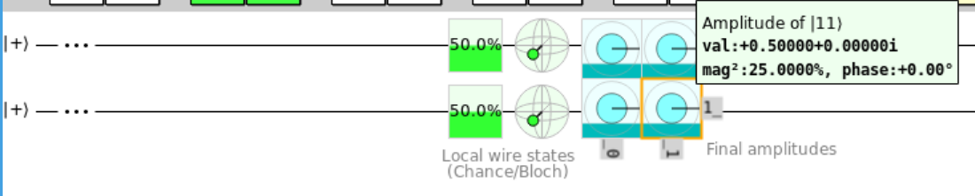
The goal of this task is to change our state like so:
\[ \frac{|00\rangle + |01\rangle + |10\rangle + |11\rangle}{2} \rightarrow \frac{|00\rangle + |01\rangle + |10\rangle - |11\rangle}{2} \]
Looking at the circuit above, this is the same thing as negating the val: field for the amplitude of \(|11\rangle\)
As we learned in task 1.7, changing the sign of the state can be accomplished with the Z gate. Let's see what happens when we apply the Z gate to our qubit.

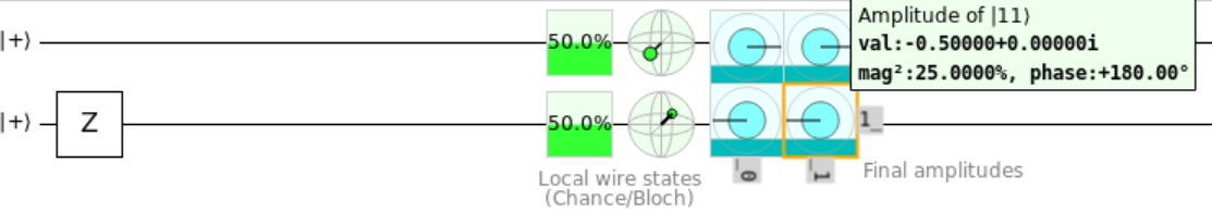
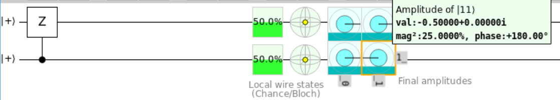
Placing the Z gate on first and second qubit negated the value of the second column and second row respectively. However, we just want to isolate the \(|11\rangle\) state.
This can be done with a Controlled Z gate. Similar to CNOT gate, CZ(x, y) preforms a Z operation on qubit \(y\) if qubit \(x\) is in the \(|1\rangle\) state.
To understand this, let's look at the matrix representation of all possible inputs. If we represent our two-qubit state as a 4-dimensional vector \(|\Psi\rangle\), where
and \(\alpha_{xy}\) is the normalized probability amplitude of measuring our qubits in the state \(|XY\rangle\), we can see the effect of the Controlled Z gate on all our possible basic inputs.
We can see that only the \(|11\rangle\) state was changed, just as intended.
Fill in the operation as shown below. You can use the intrinsic CZ gate or the Z gate with the Controlled modifier.
operation TwoQubitGate2 (qs : Qubit[]) : Unit is Adj {
    Controlled Z([qs[0]], qs[1]);
    // alternatively: CZ(qs[0], qs[1]);
}
Task 2.3: Two-qubit gate - 3⌗
Again, we are given an array of two qubits, this time in some arbitrary state
\[ |\Psi\rangle = \alpha|00\rangle + \beta|01\rangle + \gamma|10\rangle + \delta|11\rangle \]
And we are tasked with transforming it to the state
\[ |\Psi'\rangle = \alpha|00\rangle + \gamma|01\rangle + \beta|10\rangle + \delta|11\rangle \]
Which effectively swaps the probability of finding our qubits in state \(|01\rangle\) and \(|10\rangle\). In vector form, this can re represented like this:
If you recently took a linear algebra course, you may have been able to derive the matrix to achieve this transformation. This is the matrix representation of the SWAP gate.
The task also hints that this test can be passed with "several (possibly controlled) Pauli gates". Much like the classical SWAP gate, a quantum SWAP gate can be expressed with CNOT gates.
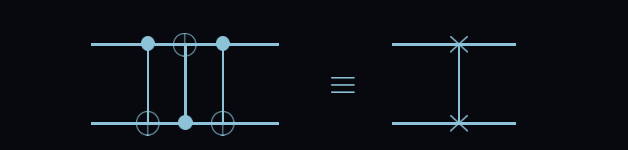
Write the operation like so to pass the test.
operation TwoQubitGate3 (qs : Qubit[]) : Unit is Adj {
    CNOT(qs[0], qs[1]);
    CNOT(qs[1], qs[0]);
    CNOT(qs[0], qs[1]);
    // alternatively: SWAP(qs[0], qs[1]);
}
Task 2.4: Toffoli Gate⌗
For this task, we have been given a generous three qubit state \(|\Psi\rangle\) to work with.
\[ |\Psi\rangle = \alpha|000\rangle + \beta|001\rangle + \delta|011\rangle + \epsilon|100\rangle + \zeta|101\rangle + \eta|110\rangle + \theta|111\rangle \]
The goal is as follows:
Flip the state of the third qubit if the state of the first two is |11⟩
This means changing the state to
\[ |\Psi\rangle = \alpha|000\rangle + \beta|001\rangle + \delta|011\rangle + \epsilon|100\rangle + \zeta|101\rangle + \theta|110\rangle + \eta|111\rangle \]
In previous tasks, we have used Controlled gates to implement condition based operations. How might we add another conditional layer? By simply adding another control bit!
This is the Toffoli gate, a universal gate in both classical and quantum computing.
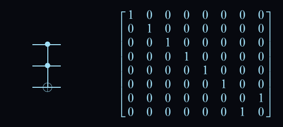
The Toffoli gate negates the third qubit if and only if the first two qubits are in the \(|11\rangle\) state.
Here is the correct code for the task:
operation ToffoliGate (qs : Qubit[]) : Unit is Adj {
    CCNOT(qs[0], qs[1], qs[2]);
    // alternatively (Controlled X)(qs[0..1], qs[2]);
}
Task 2.5. Fredkin gate⌗
Like the Toffoli gate from the last task, the Fredkin gate is a universal gate in classical and quantum computing.
The Fredkin gate, also known as the Controlled Swap, swaps the 2nd and 3rd qubit only if the first qubit is in the \(|1\rangle\) state.
\[ |\Psi\rangle = \alpha|000\rangle + \beta|001\rangle + \delta|011\rangle + \epsilon|100\rangle + \zeta|101\rangle + \eta|110\rangle + \theta|111\rangle \]
\[ \downarrow \]
\[ |\Psi'\rangle = \alpha|000\rangle + \beta|001\rangle + \delta|011\rangle + \epsilon|100\rangle + \eta|101\rangle + \zeta|110\rangle + \theta|111\rangle \]
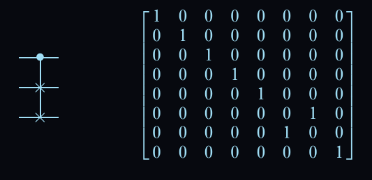
Although the Fredkin gate is extremely common in larger quantum circuits, the easiest way to express it here is with the following code:
operation FredkinGate (qs : Qubit[]) : Unit is Adj {
    Controlled SWAP([qs[0]], (qs[1], qs[2]));
}
Conclusion⌗
In this article, I covered some of the fundamental concepts of quantum mechanics by using example problems from Microsoft's Q# Quantum Katas.
I went over some of the basic quantum gates and how they can be applied to your quantum programs.
I am still new to this field, so please do not hesitate to contact me with questions or corrections.